Structural design and drawings · Killarney Vale NSW
In short: Our client in Killarney Vale NSW needed structural drawings for a timber-framed addition to their house. We designed a suspended timber floor on 15 adjustable steel stumps set in 450 mm concrete piers, H3 treated floor and roof framing, LVL roof beams and plywood bracing, in an eleven-sheet set issued for approval.
- Service
- Structural design and drawings
- Location
- Killarney Vale NSW
- Completed
- September 2026
- Project
- Timber-framed addition to an existing house, with a suspended timber floor
- Site class
- Presumed Class M, to be confirmed by the contractor before excavation
- Footings
- 15 piers, 450 mm diameter mass concrete, at least 1000 mm deep and down to hard strata, into soil or rock of at least 150 kPa
- Stumps
- Adjustable head steel stumps, 75 x 75 x 2.5 SHS, set at least 600 mm into each pier
- Floor framing
- Beams of two 290 x 45 mm MGP10, joists of 240 x 45 and 190 x 45 mm MGP10 at 450 mm centres, all H3 treated
- Roof framing
- 290 x 45 mm MGP10 H3 rafters at 600 mm centres, with beams of two 300 x 45 mm LVL13 H3
- Wind classification
- N2
- Standards referenced
- NCC 2022 Volume Two, AS 1684, AS 1720, AS 3600-2018, AS 4100-2020, AS 2870-2011
- Drawings
- 11 sheets, issued for approval and revised twice
The brief
Our client in Killarney Vale, on the Central Coast, planned a timber-framed addition to their house. The addition has a suspended timber floor, stud walls and its own roof framing, and it ties into the existing house. They needed structural drawings to go with the architectural plans for approval.
The set was issued for approval and then revised twice. The latest revision updated the member sizing for H3 treated pine.
Why it needed a structural engineer
An addition on a raised timber floor carries its loads down through beams, posts and stumps into the ground, and every one of those members has to be sized and connected. The drawings' general notes set the design live loads at 1.5 kPa for internal floors, 2.0 kPa for external floors and 0.25 kPa for the roof, and call for all workmanship and materials to follow NCC 2022 Volume Two and local council requirements.
The ground matters too. Under NCC 2022, the ABCB Housing Provisions say in clause 4.2.2 that the foundations where footings are to be located must be classified in accordance with AS 2870. This design is based on a presumed Class M site.
For approval, NSW Planning lists alterations and additions to a house among the projects that can be complying development if they meet the standards. The general notes say these drawings are subject to approval by the relevant local authority or council before construction, and no work starts until written authorisation to proceed has been issued.
Structural drawings for alterations and additions are part of our structural design and consultation service.
What we designed
We prepared an eleven-sheet set: a cover sheet, general notes, a foundation layout plan, a subfloor framing plan, a roof framing plan, a wall bracing plan, four sheets of structural connection details, and a wall framing and lintel schedule.
Footings and stumps
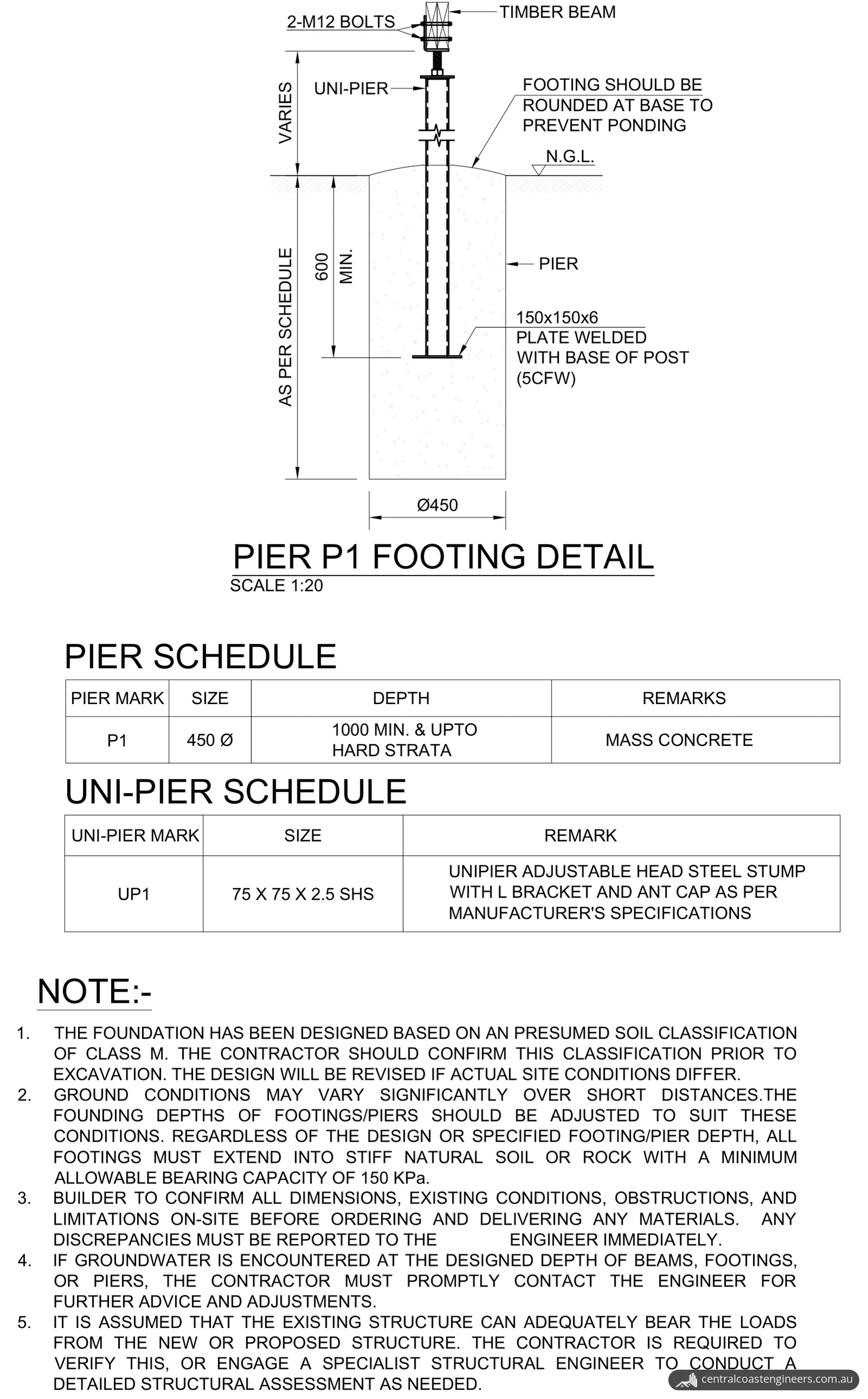
- Ground. The foundation is designed on a presumed Class M site. The contractor should confirm this before excavation, and the design will be revised if actual site conditions differ. Ground conditions may vary significantly over short distances, so founding depths are to be adjusted to suit, and all footings must reach stiff natural soil or rock with an allowable bearing capacity of at least 150 kPa.
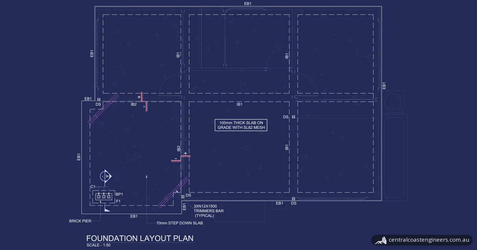
- Piers. Fifteen P1 piers are set out in three rows of five. Each is 450 mm in diameter, of mass concrete, at least 1000 mm deep and taken down to hard strata. The top of each footing is rounded to prevent water ponding.
- Stumps. Each pier carries a UP1 adjustable head steel stump of 75 x 75 x 2.5 SHS with an L bracket and ant cap, installed to the manufacturer's specifications. A 150 x 150 x 6 mm plate is welded to the base of the stump, which sits at least 600 mm into the pier.
- Groundwater. If groundwater is found at the design depth of the footings or piers, the contractor must contact the engineer.
Floor framing
| Mark | Element | From the drawings |
|---|---|---|
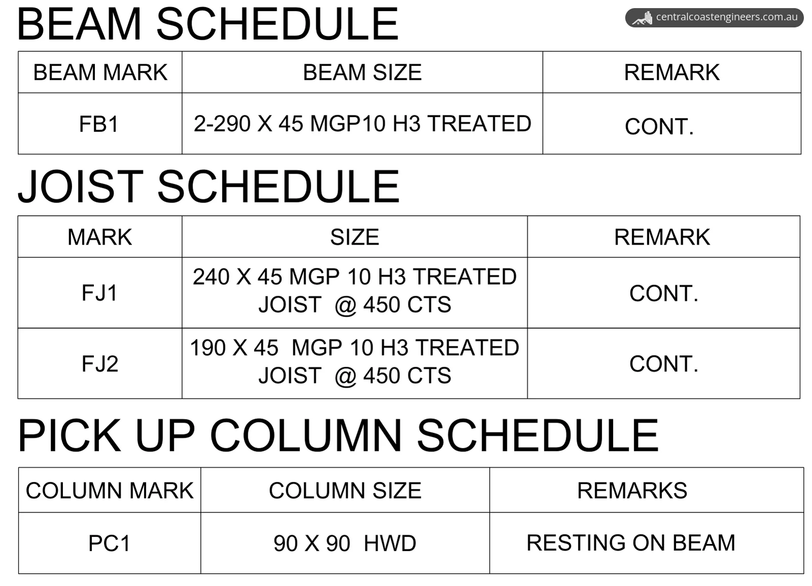
| FB1 | Floor beam | Two 290 x 45 mm MGP10, H3 treated, continuous |
| FJ1 | Floor joist | 240 x 45 mm MGP10, H3 treated, at 450 mm centres |
| FJ2 | Floor joist | 190 x 45 mm MGP10, H3 treated, at 450 mm centres |
| PC1 | Pick-up column | 90 x 90 mm hardwood, resting on the beam |
| UP1 | Steel stump | 75 x 75 x 2.5 SHS adjustable head stump |
| P1 | Pier | 450 mm diameter mass concrete |
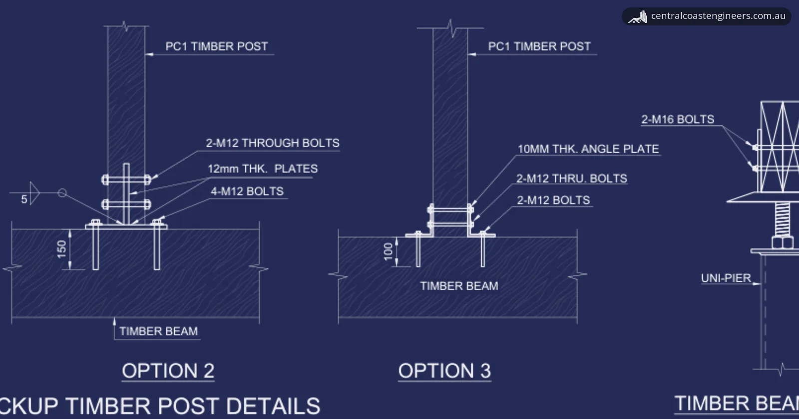
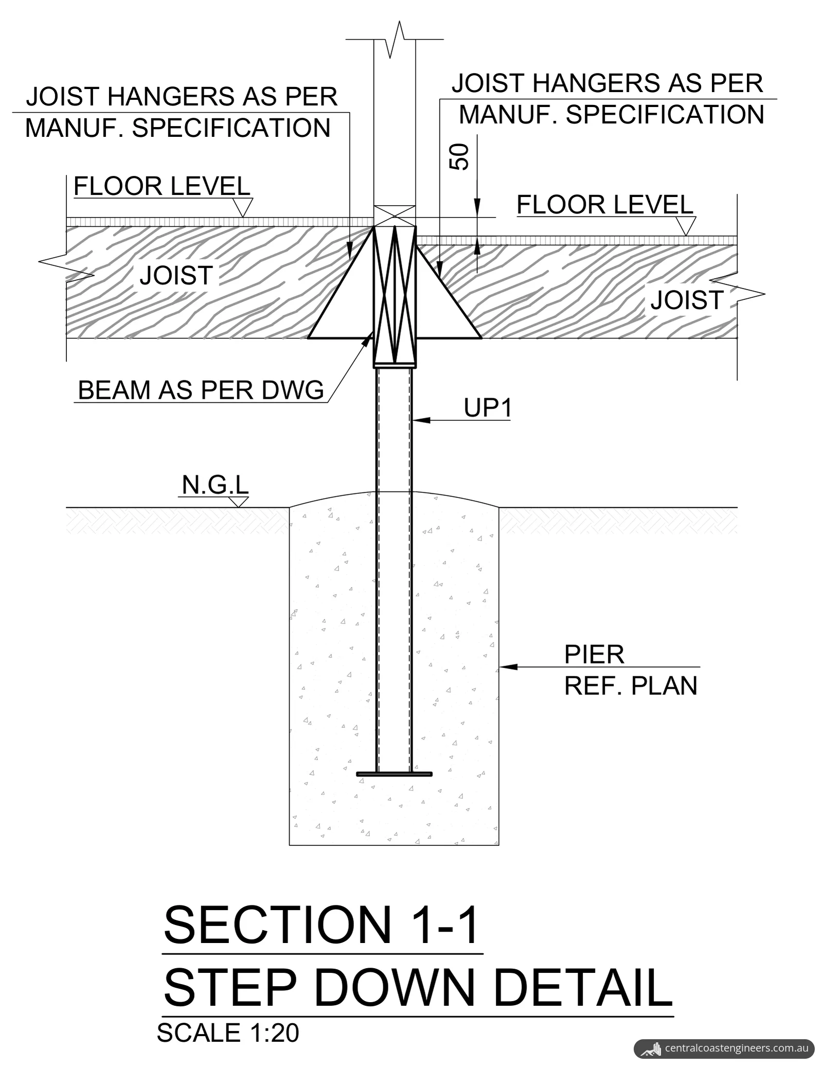
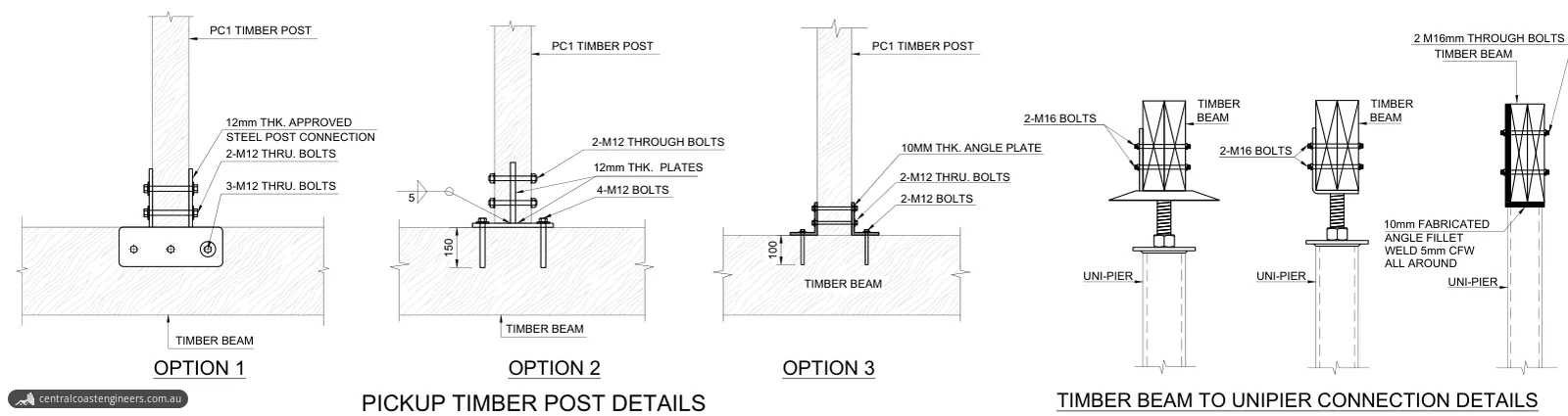
The floor steps down 50 mm in two marked places. Section 1-1 shows how: the joists on each side are hung off the beam with joist hangers to the manufacturer's specification, and the beam sits on a steel stump. The floor beams are bolted to the stump heads with two M16 bolts, or through a fabricated 10 mm angle with a 5 mm fillet weld all round. For the PC1 posts, the drawings give three ways to fix them to the beam, using a 12 mm steel post connection, welded 12 mm plates or a 10 mm angle plate, with M12 bolts.
Roof framing
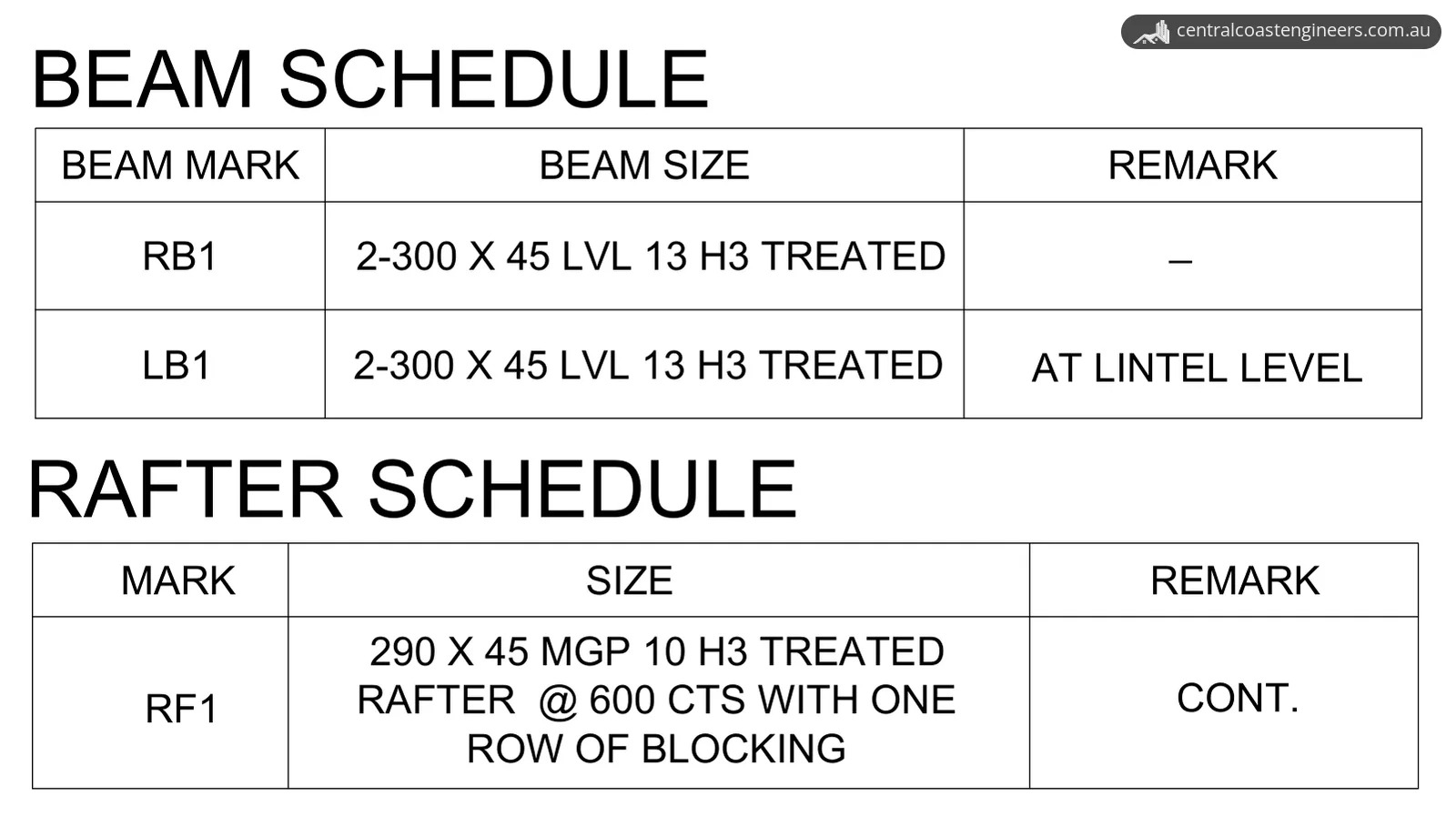
- Rafters. RF1 rafters are 290 x 45 mm MGP10, H3 treated, at 600 mm centres with one row of blocking.
- Beams. RB1 and LB1 are each two 300 x 45 mm LVL13, H3 treated. LB1 sits at lintel level, and the plan dimensions 4240 mm between LB1 and RB1.
- Fixings. Rafters and joists connect to beams with hangers and framing anchors detailed on the connection sheets, and stud clusters go at both ends of timber beams spanning more than 4 m where no supporting column is present.
Walls and bracing
- Bracing. The wall bracing plan places four type B structural plywood bracing panels, each at least 900 mm long. The plywood is nailed to the frame with 30 x 2.8 mm galvanised flat-head nails, and bracing not shown is to be in accordance with AS 1684.
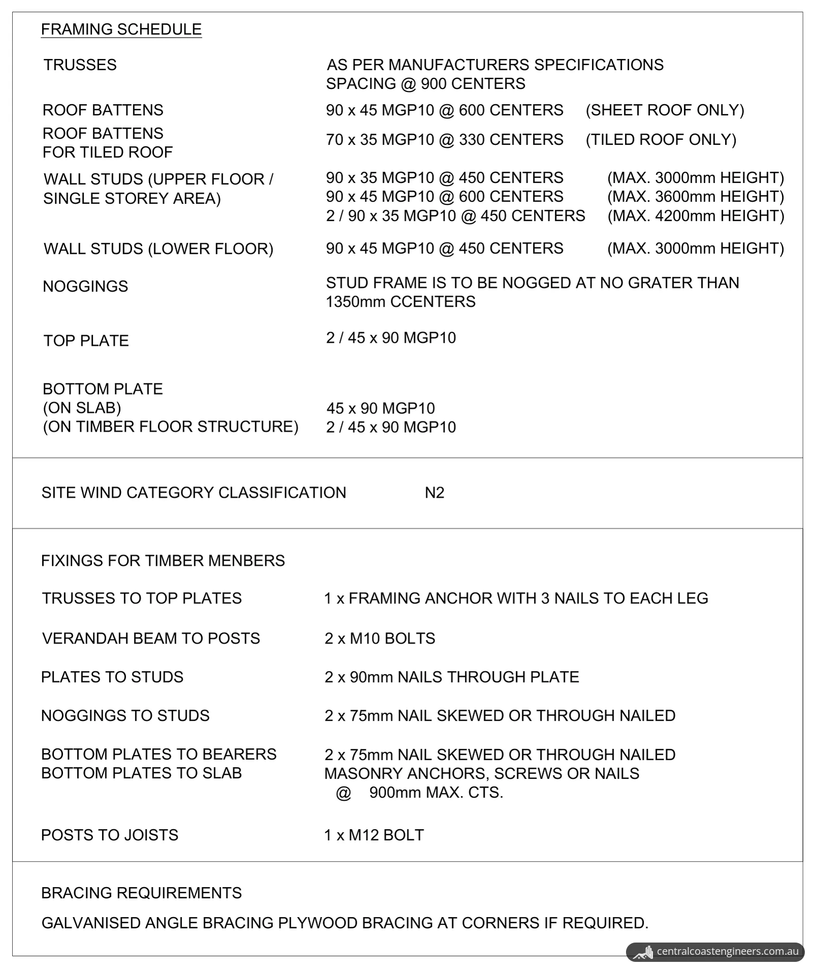
- Framing. The framing schedule sizes studs by wall height, for example 90 x 35 mm MGP10 at 450 mm centres for single-storey walls up to 3000 mm high. Noggings are at no more than 1350 mm centres, the top plate is two 45 x 90 mm MGP10, and the bottom plate on a timber floor is two 45 x 90 mm MGP10.
- Openings. The lintel schedule sizes window and door lintels and jamb studs by clear span, up to 3000 mm. For openings wider than 3.0 m, triple studs go on each side.
- Wind. The site wind classification is N2.
The timber notes call for timber used on site to be treated in accordance with AS 1684, with H3 for external, above-ground timber exposed to weather or damp, and H4 for timber in ground contact. Structural timber is to comply with AS 1720 and AS 1684, concrete with AS 3600-2018 and steelwork with AS 4100-2020.
What had to be checked on site
The drawings assume that the existing house can adequately carry the loads from the new addition. The contractor is to verify this before work starts, or engage a structural engineer for a detailed assessment. The builder is also to confirm all dimensions, existing conditions and obstructions on site before ordering materials, and report any discrepancies to the engineer.
The result
Our client received an eleven-sheet structural drawing set, in its second revision and issued for approval, covering the piers, stumps, floor and roof framing, bracing and connections for the addition. Under its notes, inspections during construction are to be confirmed 72 hours ahead, and if required the contractor certifies at completion that the as-built works match the approved drawings.
Planning an addition on the Central Coast?
Our structural design and consultation service prepares structural drawings for alterations and additions, including footings, subfloor and roof framing. Send us your architectural plans, any soil or geotechnical report, and whether you're going through a development application or complying development. We'll tell you what the drawings would involve and give you a no-obligation quote. During the build, our inspection reports and certifications service covers construction-stage inspections. You can request a quote online or call 02 4326 9026.
Photos and drawings
From the report
Sample pages from what the client received (personal details removed).
Frequently asked questions
Can a house addition be complying development in NSW?
It can be. NSW Planning describes complying development as a combined planning and construction approval for straightforward development, and lists alterations and additions to a house among the types it covers. Most complying development types and their development standards are set out in a state environmental planning policy, so the project has to meet those standards to qualify.
Who approves complying development, and how long does it take?
NSW Planning says complying development can be determined through a fast-track assessment by a council or an accredited certifier, and approvals can be issued in as little as 20 days.
What does a Class M site mean for footings?
Under NCC 2022, the ABCB Housing Provisions require the foundations where footings and slabs go to be classified in accordance with AS 2870. Class M is a moderately reactive clay or silt site, which can experience moderate ground movement from moisture changes. Class M sites need further division by the depth of expected movement, and for Class M-D, footing and slab design is beyond the scope of the Housing Provisions and AS 2870 applies.