Retaining wall design · Macmasters Beach NSW
In short: The client needed structural drawings for new retaining walls in Macmasters Beach NSW, in core-filled concrete block and in sandstone blocks, up to 1.2 m high. We designed the reinforced block wall footings, the engineered fill bases under the sandstone and the drainage behind the walls, in a nine-sheet drawing set for approval before construction.
- Service
- Retaining wall design
- Location
- Macmasters Beach NSW
- Completed
- September 2026
- Wall types
- Core-filled concrete block walls (two section types) and sandstone block walls
- Wall heights
- Block wall sections scheduled for 800, 1000 and 1200 mm; sandstone wall sections for 1.0 m and 1.2 m maximum
- Soil class designed for
- Class M (presumed, to be confirmed by the contractor before excavation)
- Bearing capacity
- At least 250 kPa allowable, in stiff natural soil or rock
- Block walls
- Grade 15 (15 MPa) standard blocks to AS 3700, core fill of at least 20 MPa, scheduled bars N12 at 400 mm centres
- Block wall backfill density
- 18 kN/m³
- Sandstone walls
- 500 x 500 x 1000 mm sandstone blocks on an engineered fill base, 800 x 400 mm or 1250 x 250 mm depending on wall height
- Sandstone wall design basis
- AS 4678:2002; 22 kN/m³ retained backfill, Ka = 0.29, 2 kPa live load surcharge
- Drainage
- Granular backfill and a 100 mm drain behind every wall
- Designed for
- Retaining soil only, with no structures behind the walls
- Main standards referenced
- AS 4678:2002 (earth-retaining structures), AS 3700 (masonry), AS 3600 (concrete)
The brief
The client needed structural drawings for proposed retaining walls at a property in Macmasters Beach, on the NSW Central Coast. The design uses two wall types: core-filled concrete block walls and sandstone block walls, each up to 1.2 m high.
The drawings had to show the builder how each wall is founded, built and drained, and go forward for approval before construction. The set was revised once in response to the client's comments.
Why it needed a structural engineer
In NSW, a retaining wall needs no planning consent only if it meets every standard for exempt development in the State's Codes SEPP. The NSW Department of Planning's page on earthworks, retaining walls and structural supports lists the main standards, such as being at least 2 m horizontally from any other retaining wall on the site, and says all works must be structurally adequate. The NSW Planning Portal says earthworks and structural supports more than 600 mm above or below ground level may be done as complying development, under the development standards in Schedule 9 of the Codes SEPP.
The walls on this job are up to 1.2 m high, twice that 600 mm figure. The structural drawings set the footing or base, reinforcement and drainage for each wall height, so the approving authority can check the design and the builder can follow it.
What we designed
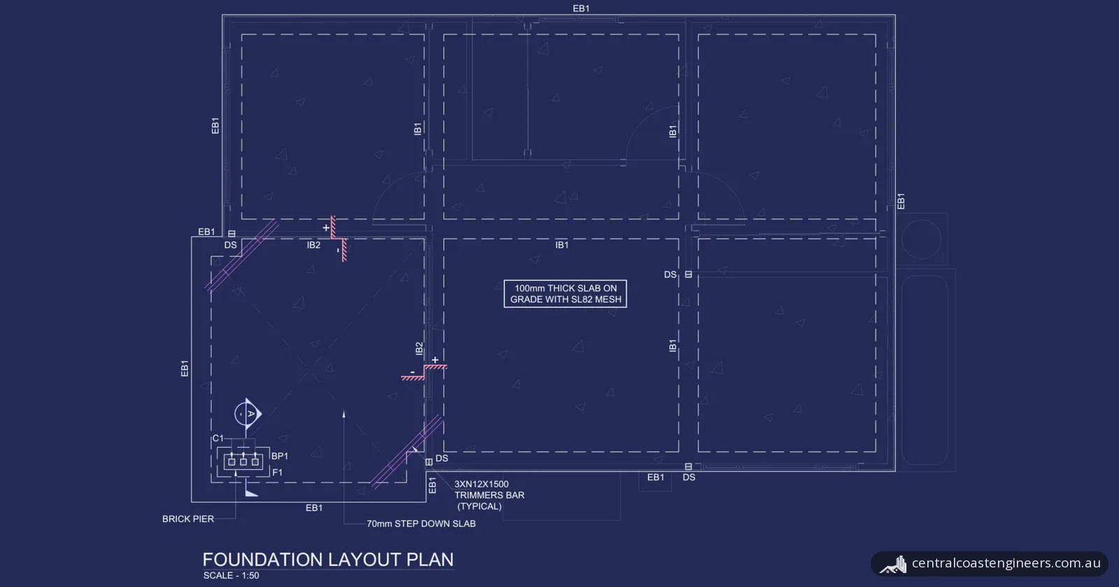
The drawing set has nine sheets: a cover sheet, general notes, a layout plan, two core-filled block wall sections (Type 1 and Type 2), two sheets of typical block wall details, and sandstone wall sections for heights of 1.0 m and 1.2 m.
Core-filled block walls
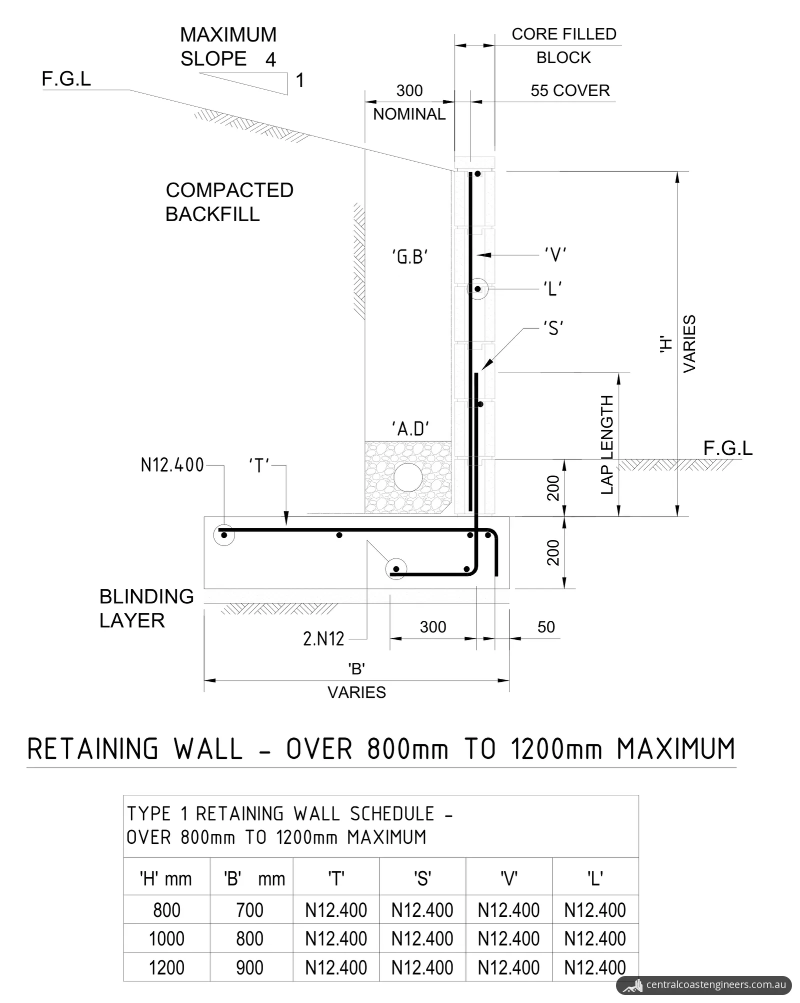
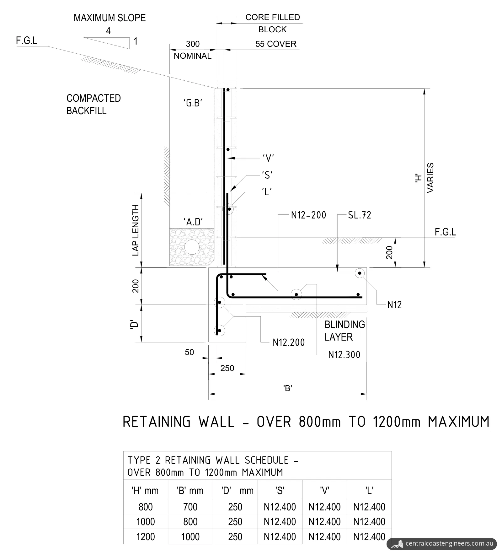
- Blocks and core fill. The walls use Grade 15 (15 MPa) standard blocks as set out in AS 3700, with core fill of at least 20 MPa compressive strength and a maximum aggregate size of 10 mm. Every scheduled bar is N12 at 400 mm centres, with 55 mm cover to the wall reinforcement.
- Two footing arrangements. Each wall stands on a 200 mm thick reinforced concrete base, with its top 200 mm below finished ground level in front of the wall. In Type 1, the base runs back under the retained soil. In Type 2, the base runs forward under the lower ground, is deepened by 250 mm under the wall, and also carries SL72 mesh.
- Design values. The block wall notes give a backfill density of 18 kN/m³ and a minimum allowable bearing capacity of 250 kPa.
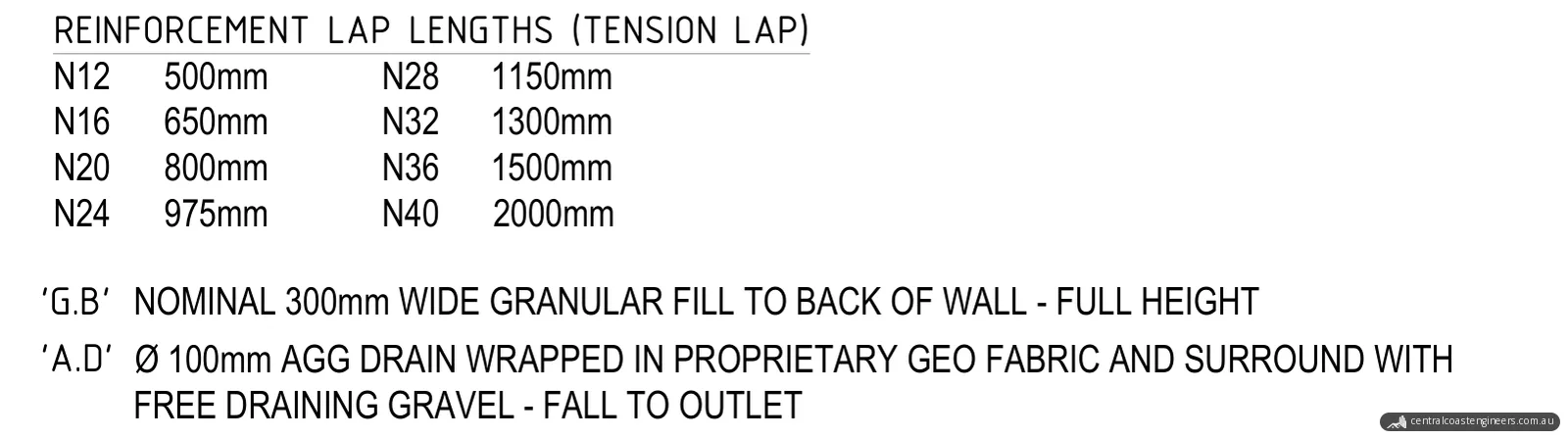
- Drainage. A nominal 300 mm wide band of granular fill runs the full height behind the wall. At its base is a 100 mm ag drain wrapped in geofabric, surrounded by free-draining gravel and falling to an outlet.
- Founding. All footings are founded into dense natural ground, with reference to the soil test report. Where a footing does not reach natural ground, it is made deeper.
- Steps and details. Where a footing steps, the step must be no greater than the footing depth and the step width no less than it. The typical details also cover footing corners, wall corners and wall ends, control joints, and four methods for stepping a footing.
- Soil only. The block walls retain earth only. They are not designed to carry any structural loads beyond soil retention, and no block wall is to be filled higher than 1200 mm without suitable shoring.
The schedules size the base for each wall height:
| Wall height (H) | Type 1 base width (B) | Type 2 base width (B) | Type 2 deepening under the wall (D) | Scheduled bars |
|---|---|---|---|---|
| 800 mm | 700 mm | 700 mm | 250 mm | N12 at 400 mm centres |
| 1000 mm | 800 mm | 800 mm | 250 mm | N12 at 400 mm centres |
| 1200 mm | 900 mm | 1000 mm | 250 mm | N12 at 400 mm centres |
Sandstone walls
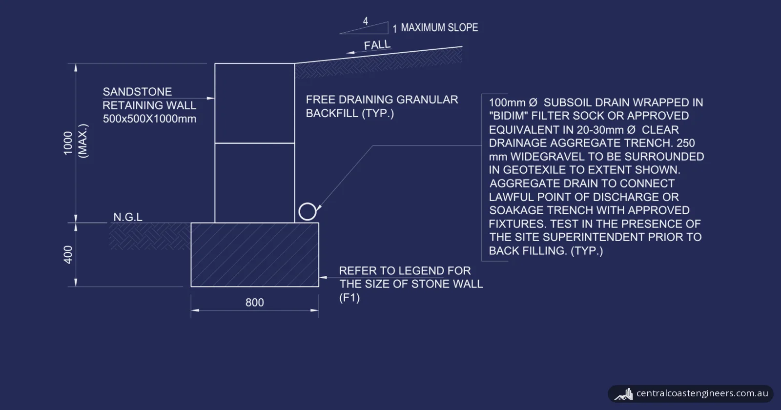
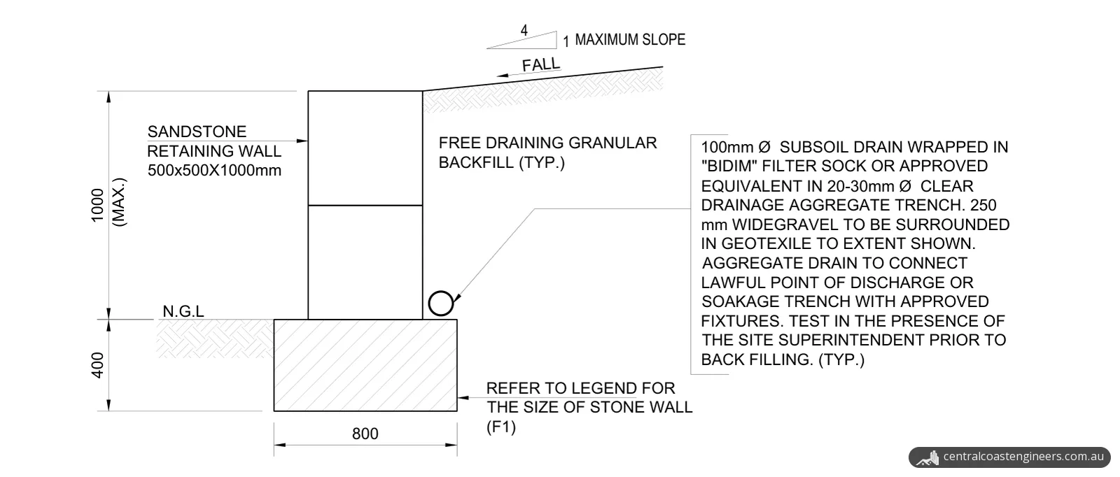
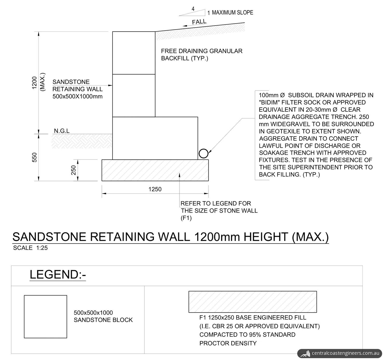
- Blocks and bases. The walls are built from 500 x 500 x 1000 mm sandstone blocks. The 1.0 m wall is two courses on an 800 mm wide, 400 mm deep base of engineered fill, with the top of the base at natural ground level. The 1.2 m wall has a wider bottom course on a 1250 mm wide, 250 mm deep base, with its underside 550 mm below natural ground level.
- Engineered fill. The base is engineered fill with a CBR of 25 or an approved equivalent, compacted to 95% standard Proctor density.
- Drainage. Free-draining granular backfill sits behind the stone. A 100 mm subsoil drain in a filter sock runs in a trench of 20 to 30 mm clear drainage aggregate, with the 250 mm wide band of gravel wrapped in geotextile. The drain connects to a lawful point of discharge or a soakage trench, and is tested in the presence of the site superintendent before backfilling.
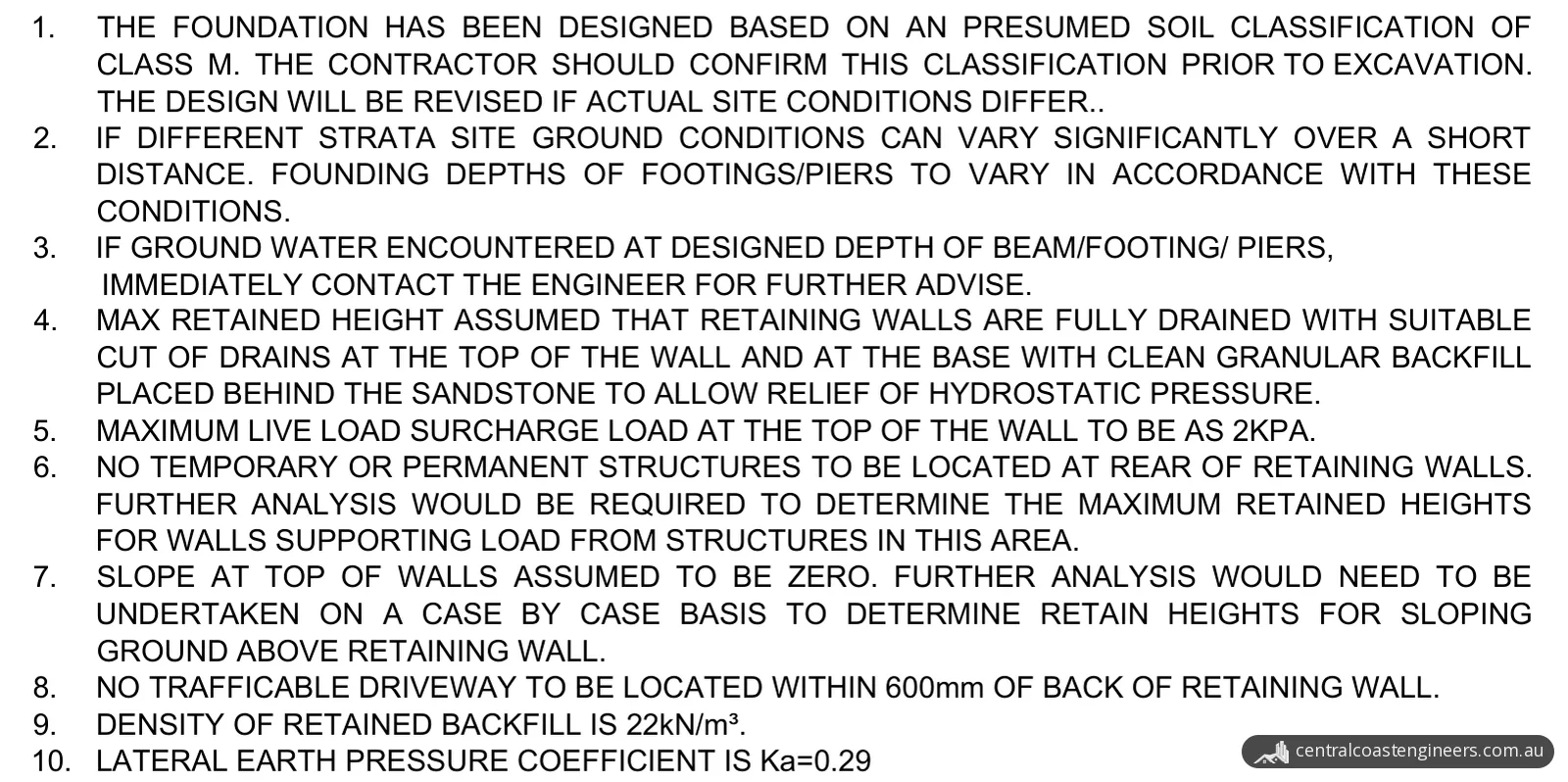
- Design basis. The design parameters are based on AS 4678:2002, Earth-retaining structures. They use a retained backfill density of 22 kN/m³ and a lateral earth pressure coefficient (Ka) of 0.29. The maximum retained height assumes the walls are fully drained, the live load surcharge at the top of the wall is limited to 2 kPa, and the ground at the top of the wall is level; sloping ground above a wall needs further analysis, case by case.
- What stays clear of the wall. No temporary or permanent structures are to sit at the rear of the walls; walls supporting load from structures there would need further analysis. No trafficable driveway is to be within 600 mm of the back of a wall. Any load above the surcharge load within 1.5 times the wall height behind the wall must be piered below the structural load line, and no excavation is to go below the 45° zone of influence from the base of the wall.
What has to be confirmed on site
The design depends on the ground, so the drawings list what the builder and the client must check:
- Soil class. The foundations are designed for a presumed Class M soil classification. The contractor should confirm it before excavation, and the design will be revised if actual site conditions differ.
- Founding depth. Ground conditions can vary significantly over short distances, so founding depths are to suit the conditions found. Whatever depth is specified, all footings must extend into stiff natural soil or rock with a minimum allowable bearing capacity of 250 kPa.
- Geotechnical check. The client or their representative is to engage a geotechnical consultant to evaluate the foundation soils before construction.
- Groundwater. If groundwater is found at the design depth of the footings, the contractor must contact the engineer for advice.
- Dimensions. The builder confirms all dimensions, existing conditions and site limitations before ordering materials, and reports any discrepancies to the engineer.
The result
The client received the nine-sheet drawing set, revised in response to their comments. It gives the builder the base size and reinforcement for each block wall height, the bases for both sandstone wall heights, and the drainage and site checks for every wall. Under the general notes, the drawings are subject to approval by the relevant local authority or council before construction, and no work is to start until written authorisation to proceed has been issued. On completion, if required, the contractor certifies that the as-built works match the approved issued-for-construction drawings.
Planning a retaining wall on the Central Coast?
Our structural design and consultation service includes retaining wall drawings, and we work across the Central Coast, Newcastle, Lake Macquarie and Greater Sydney. Send us photos of the area, the heights you need to retain, any survey or site plan you have, and a soil or geotechnical report if there is one. You can request a quote online or call 02 4326 9026.
Photos and drawings
From the report
Sample pages from what the client received (personal details removed).
Frequently asked questions
Do I need approval to build a retaining wall in NSW?
Not if the wall meets every standard for exempt development in the State's Codes SEPP. The NSW Department of Planning says that, among other things, an exempt retaining wall must not be on a heritage item, must be at least 40 m from a body of natural water, must not redirect surface or ground water or send sediment onto an adjoining property, and must be at least 2 m horizontally from any other retaining wall on the site. The works must also be structurally adequate and comply with the Building Code of Australia.
What if a retaining wall is higher than 600 mm in NSW?
The NSW Planning Portal says earthworks and structural supports more than 600 mm above or below ground level may be done as complying development, and that Schedule 9 of the Codes SEPP sets the development standards for excavation, fill, retaining walls, structural support and drainage. The NSW Department of Planning says a complying development certificate (CDC) can be obtained through your local council or an accredited certifier, without a full development application.
Which Australian Standard covers retaining wall design?
AS 4678, Earth-retaining structures. Standards Australia describes AS 4678-2002 as specifying the design criteria and setting out guidance for the design of earth-retaining structures, for use by engineers and designers. It is included in the NCC Primary References Set.